|
Part 2
3.2 Compressive stresses in the columns - less than
1/3 of the yield stress
The mass above the walls at floors 94-98 is thus about 19
800 tons supported by 236 wall columns (total cross area
3.54 m²). Therefore each wall column on average
supports 84 tons.
The compressive stress in the wall column at floors 94-98
with cross area 150 cm² is thus abt 560 kgs/cm² or
56 MPa or 22.5% of the yield stress (abt 248 MPa) of the
steel.
NIST suggests that the static loads will be increased 35%
in the East wall and 30% in the West wall (all 100% intact)
due to load transfers just prior collapse, i.e. the
compressive stresses in columns there becomes 75.6 and 72.8
MPa, which is still only 30.5% and 29.4% if the yield
stress. Actually these are the increased stresses you would
expect due to wind under hurricane conditions.
The mass above the core is only13 200 tons supported by
the 47 core columns with total area 2.1 m². On average
each core column carries abt 280 tons so the average
compression is 629 kgs/cm² or 63 MPa. However the outer
core columns carry more mass and the outer corner core
columns the most load, e.g. no. 501 with cross area 950
cm². It may carry as much as 700 tons.
The compressive stress in the no. 501 core column at
floors 94-98 is thus abt 736 kgs/cm² or 74 MPa or 30%
of the yield stress of the steel. It is assumed that the
compressive stress in the other core columns is abt the
same.
NIST suggests that the load in the core is reduced 20%
just prior collapse, i.e. the stresses are reduced. However,
some core columns may have been damaged in the initiation
zone so in all probability the stresses in the remaining
columns may have remained at 30% yield stress.
The reason why original the static stresses are higher in
the core than in the perimeter walls is that the wall
columns are also designed to absorb dynamic wind loads.
4. The Towers were built very strong in the
1960's
The above is a clear indication how the Towers were
originally built by serious architects and engineers in the
1960's. Compressive static stresses in the columns were less
than 1/3 of the yield stress of the steel before (obviously)
... and after serious damage (not so
obvious but shown here)! The buckling stress of the column
is virtually the same as the yield stress as the columns
were arranged with spandrels. One reason why the static
stresses were so low was that the designers had no access to
computers to optimize (slender down) the construction.
Manual calculations were done and to be on the safe side you
added steel and built strong! And steel was quite cheap at
that time. And US steel was good quality. The assumed yield
stress 248 MPa was probably much higher in reality.
NIST never checked the yield stress of the steel from the
initiation zone in the rubble!
There was therefore plenty redundancy. A plane may crash
into the bird cage and nothing happens. A big fire may break
out and nothing happens. Why? Because the normal compressive
stress in the supporting vertical structure is so low and if
any column breaks or buckles, its load is transmitted to
adjacent columns via the spandrels and the stress in
adjacent columns increase a little. No global collapse is
possible under any circumstances.
Evidently the columns got stronger (thicker plates, steel
with higher yield stress) further down when the 'mass above'
increases, but it is certain that the compressive stresses
in the Towers never exceed 1/3 of the yield stress. Same
applies for the buckling stresses.
5. No release of potential energy due to
downward movement - influence of heat
The mass/load above a column evidently compresses it. The
column acts as a spring. As long as the compressive stress
is less than yield stress, the compression is elastic and
hardly noticeable. As seen above the actual compressive
stresses were only <30% of yield stress and I assume this
was common practice in steel tower construction in US and
elsewhere in the 60's.
How is the yield stress of steel affected by heat? In the
writer's opinion it is not affected very much at about
500°C. This is confirmed by any fire test - the test
chamber and what's in it never collapses due to the heat
inside up to 1000°C. The heat inside is normally by
kerosene set on fire.
English
authorities concur: "Although the formulae cannot
provide perfect fitting with the test data at all
temperatures, the correlation at temperatures above
400°C is in good agreement. Generally, the lack of
accuracy at low temperatures below 400°C will not
hinder the accurate prediction of fire resistance of steel
structures in practice. This is because the actual loads
applied to most buildings are commonly below 60%
of the ultimate loads they are designed for at
ambient temperature. That means the structures
will generally have a minimum inherent fire resistance of
500°C."
As noted above the stresses in the WTCs were less than
30% of the yield stress. But let's assume the yield stress
is reduced 20% due to heat. The compressive stress in the
allegedly heated core columns is still then less than 40% of
the yield stress. The wall columns are lesser stressed.
The purpose of fire proofing of steel is not to prevent
collapse or melting (!) of the steel. The purpose is only
the delay transmission of heat and to allow the heat to
dissipate to adjacent structure. In the WTCs no structure
was heated >500°C at any time according NIST even if
the fire proofing were missing.
It is very easy to check in a fire test chamber how a
steel column under compression at 30% the yield stress
resists collapse due to heat at 500°C allegedly
existing in the Towers. The answer is that it does not
collapse. You can verify this yourself - see 6. below.
Applied to WTC1 what you would expect due to a fire
around the core columns is that they only compress and that
their cross areas expand due to heat and the downward
movement of the core is a few centimeters! It may put some
extra tension in the floor trusses and their bolted
connections pulling the perimeter walls inwards a few
centimeters - and that is all! The wall perimeter columns,
80% of them are intact and free of soot and marks of fire as
shown on many videos and subject to little heat as they are
cooled by fresh air, will then further stabilize the
core.
5.1 The columns cannot bend 180°, twist or
crumple up
Remember that the outer core columns are extremely solid,
e.g. no. 501. It is an H-beam with two flanges 17x3.5 inch
connected by a 2.2x12.6 inch web. In metric terms the
flanges are 430x90 mm and the web is 56x320 mm. Such thick
plates, 56 and 90 mm cannot buckle under any circumstance
when the compressive stress is only 30% of yield stress even
if the temperature is 500°C. The (smallest) moment of
inertia I of this section is about 120 000 cm4
and its radius of gyration is thus of the order 35 cms. With
a free length of 350 cms the slenderness ration is 10!
Removing three floors as support and the free length is 1
400 cms and the slenderness ratio is still only 40! Such a
column will not buckle! Same for the wall columns that have
a radius of gyration of abt 15 cms and a slenderness ratio
of 24 when supported by spandrels and floors.
Therefore there will be no downward movement.
5.2 There is no release of potential energy
NIST does not calculate the amount of potential
energy released due to downward movement in
their report, which is therefore incomplete. The reason
simply is that no potential energy is released. In fact, no
downward movement of a mass above is even possible due to
heat inside the cage and there should be no sudden release
of potential energy.
This is easily verified at any fire test laboratory. NIST
has never done such tests! NIST should be encouraged to do
such tests.
The 236 off wall columns are, e.g. never seen to deflect
at all prior to the sudden, explosive initial collapse of
the core columns. If the core columns collapse, as alleged,
by release of potential energy above, the wall columns
should remain intact as no release of potential energy is
acting on them! Weakening is inherently a GRADUAL process
and CANNOT BE SIMULTANEOUS EVERYWHERE throughout a given
4 000 m² large floor area! It will always be local
and topple the mass above in the direction of the local
collapse.
5.3 Possible release of potential
energy due to downward movement - 340 kWh
But let's assume that potential energy is released
vertically as all low stressed columns collapse
simultaneously.
When 33 000 tons of mass above in WTC1 falls down 3.7
metres due to gravity and crushes all the columns abt 340
kWh of energy is produced by gravity and a fair part of that
energy is consumed to crush the columns. Let's assume that
this event by gravity takes 5-6 seconds based on video clips
and that there is a certain velocity at the collision. In
reverse - to first stop and second pull the mass back up
again you need a very big engine with power 204 000 kW that
pulls up the mass above. Let's assume this engine is very
effective and that you require 120 grams of diesel oil to
produce 1 kWh. It means that 40 800 grams or 40.8 kgs
of diesel oil is required to stop and pull the mass up
again! It takes 6 seconds! It can be done. It shows how much
energy was released when the top fell. 40.8 kgs of diesel
oil.
But is this what we see on this video
or this video
of the fall of the mass above? That all the columns at the
initiation zone crumple up during 6 seconds? Evidently not!
We can see the roof of the top of the mass above
starting to move and that nothing happens at
the initiation zone = no crumbling of columns there (look,
e.g. at the right side). After 2-3 seconds the mass above
seems to disintegrate and after 4-5 seconds smoke and dust
spew out through the windows at the initiation zone, where
the wall columns are still intact. They have not
crumbled!
5.4 The wall columns didn't buckle
synchronized with the mass above - the speed of
impact
|
It is in fact a very strange release of
potential energy due to alleged downward movement
of a mass above! The wall columns at the
initiation zone did not buckle, deform or crumple
up, when the mass above has allegedly been falling
down for 4-5 seconds.
Evidently the wall columns in the initiation
zone should buckle, deform and collapse
synchronized - at the same time and speed - as the
movement of the mass above. But it never happens
and is not recorded on any video!
|
Official cause of global collapse
according NIST
"The release of potential energy
due to downward movement of the building mass
above the buckled columns exceeded
the strain energy that could be absorbed by the
structure. Global collapse ensued."
|
And then the structure below apparently collapses but we
cannot see anything as that collapse takes place behind a
screen of dust and smoke. An obvious question is - did the
columns at floors 94-98 actually crumble simultaneously due
to heat in the first place?
But let's again assume that the mass above drops down 3.7
meters due to gravity acceleration 9.8 m/s². It means
that the speed after 3.7 meters displacement is abt 3 m/s or
10 kms/h. It is not a significant speed. A collision at such
low speed is not an impact! It is a bump.
5.5 The timetable - time for cause and time for
effect
In order to establish what happened to WTC1 we need to
know two times for two events that allegedly occurred: the
time Tcause, when the potential energy was
released due to all columns in the initiation zone
collapsing simultaneously, i.e. the time of the cause
of the disaster, and the time Teffect when
this energy was applied to the structure below, i.e. the
time of the effect. NIST and Z P Bazant do not advise
these times. Nothing should evidently happen to the WTC1
before Tcause. If anything
strange happens before Tcause,
e.g. the roof is moving or smoke suddenly erupts, it cannot
be due to the columns in the initiation zone collapsing
releasing potential energy. Also the time difference
(Tcause - Teffect)
cannot be more than 0.5 seconds, because that is the time
for the potential energy to reach and impact the tower below
if we assume that the distance of fall is one floor level =
3.7 m. During this time also nothing strange can happen. The
global collapse that ensued after Teffect
according NIST has still not started. The lack of a
proper time table in both the NIST report and the Bazant
report is very disturbing. The times are evidently available
from all videos of the incident.
5.6 The rigid block above goes
missing
NIST and Bazant talk about an upper solid, rigid block
above the initiation zone that suddenly falls down as a
hammer and causes global collapse! There are many videos of
the WTC1 incident but NIST and Bazant never show us the
famous block above at times Tcause (hammer
starts to fall) and Teffect (hammer
hits)!
It is evidently quite easy to sketch in the rigid block
above at time Tcause, when it starts to
drop, on any video or photo, so that we know what they talk
about, and then to do the same at time
Teffect, when the same block impacts the
structure below, to show that the block above actually
remains intact and unchanged all the time, while the columns
are deformed below it. In below pictures of the initial
collapse the assumed initiation zone at around floor 98 is
indicated with a blue
line. The upper red
line is the original roof level. The
lower red line is around
floor 94. A green vertical
line has been added beside the right wall.
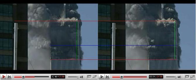
|
Picture above is at Tcause.
The upper block, width 63 meters and height
abt 63 meters, between the
upper red and
blue lines is
assumed to start dropping down because all columns
fail in the initiation zone between the
blue line and
the lower red
line. It is now the potential energy of
the mass above is allegedly released or actually
the upper block starts telescoping; sliding down
inside itself.
|
Picture above is at Tcause + 1
second. The upper block has telescoped down
1 or 2 meters. No columns are seen buckling in the
initiation zone at the right wall! On the
other hand smoke is seen pouring out through
windows in the initiation zone where the wall
columns are intact.
|
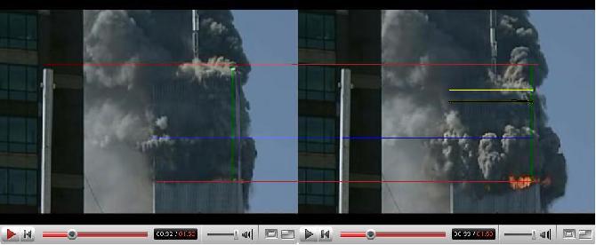
|
Picture above is at Tcause + 2
seconds. This time could maybe be
Teffect when the upper
block is assumed to impact the top of the
initiation zone -
blue line -
after a slow (!) drop of 3.7 meters - one floor
level (2 m/s or 7 kms/h) but still no columns are
seen deformed at the right wall! Now you would
expect a little jolt - the upper block bottom is in
contact with the lower structure top floor and all
steel columns in the initiation zone should
have crumpled and acted as fenders to stop further
downward movement or disappeared to allow further
downward movement. But they are still there!
|
Picture above is at Teffect +
1 or 2 seconds. The roof of the upper block
- indicated by a yellow
line - has telescoped down about 20
meters (free fall?) and you really wonder where the
bottom of the upper block is. It should be a
little above the lower red
line. If the upper block was
solid and rigid, 20 meters of the structure in the
initiation zone - below the
blue line -
should now have collapsed due to lack of alleged
strain energy and 4 or 5 floors should have
dropped, but no such damages are seen! Just
smoke pouring out. The initiation zone is still
intact! T
20 meters of the upper block has disappeared
4 seconds after Tcause ! No
collapse has started below the initiation zone the
lower red
line.
In Bazant's theory the upper block is
supposed to be intact until the end of global
collapse about 12-14 seconds after
Teffect.
|
You wonder why NIST and Bazant cannot show us in their
reports a time table for the upper block and its potential
energy initiating global collapse. This writer sees the
block disintegrating between times Tcause
and Teffect and a little later. While
reflecting about this lack of easy to understand photo
evidence in the official reports and university papers,
6. Let's do a model test!
You need:
4 off steel pipes, length 750 mm, dia 20 mm wall
thickness 1 mm (each cross area 62.83 mm²). Yield
stress 23.5 kgs/mm²
1 off 1000 x 1000 x 5 mm steel plate (weight about 40
kgs)
4 off 1000 x 1500 x 5 mm steel plates (each weight about
60 kgs)
4 off 960 x 4 x 3 mm steel flat bars (spandrels)
4 off plywood sheets 995 x 920 x 5 mm. Make some holes in
them to allow air to enter and smoke to escape! One hole can
look like as if a model air plane has made it.
You weld the pipes to the corners of the square steel
plate and you get a table with four legs. Each leg has
slenderness ratio abt. 75. Weld the spandrels between the
legs at about half height.
Put table on firm ground, e.g. cement floor.
Then weld the four other plates on the top of this table
to form a 'water tank'.
Fix the four plywood sheets between the legs of the table
as a skirt.
Decorations: The 'water tank' on the table is the
'upper mass' of WTC1. You can paint it to look like
it. The four plywood sheets - the skirt - are the walls of
the initiation zone of WTC1. You can paint that too to look
like it. It is in fact a 1/20 model of part of WTC1 'mass
above' and 'initiation zone'. The legs are four of the
columns!
Load on table: In order to compress the table legs in the
WTC1 model initiation zone at say 30% yield we need abt 1
500 kgs of weight on the table top! Thus you fill the water
tank to level about 1.5 meters and there you are: 1 500 kgs
of water + 280 kgs of steel plates = 1 780 kgs are carried
by four legs each cross area 63 mm². Stress in columns
= 7.06 kgs/mm² = 30% of yield stress.
Table, 0.755, m and tank, 1.5 m, make a 2.255 m high
model of WTC1 mass above and initiation zone! .
Then you fit a suitable thermometer to record the
temperature inside the initiation zone.
The volume of the initiation zone is only 0.75
m3 and it is quite easy to heat it up to
500°C!
Cost of model is not too much: 7 m² of 5 mm steel
plate (280 kgs) - say $400:- Pipes $20:-, Skirt $80:-
welding rods, paint and misc. $100:- . Labour $ 0:-, if you
ask daddy to assemble it.
Now the fun starts! We are going to put this model of
WTC1 on fire! Or at least the initiation zone.
Put a tray of one gallon diesel oil on the cement floor
between the legs of the model and fill the rest of the
initiation zone with paper, rugs and similar.
Now put the diesel oil on fire! See how the initiation
zone heats up, air is drawn in and smoke escapes through the
holes. Very soon the temperature is 500°C uniformly
inside the initiation zone and the table legs are heated up
to same temperature. The plywood will burn very slowly.
The purpose of the model test is of course to establish
the stiffness of the table leg pipes (the columns of the
initiation zone) under heat and to see if suddenly, at, e.g.
temperature 500° C, the mass above (luckily most water
in this test for children) drops down, at a significant
speed and with an enormous kinetic energy, and impacts on
the cement floor with an enormous dynamic load.
Or does nothing of that sort happen? Maybe the table legs
will just bulge. You will find out (the latter)!
7. Strain energy absorbed by structure
below and its compression
It should thus be clear that the only structure below our
wall cage bars are the wall cage bars and it is very easy to
calculate what strain energy they can absorb before rupture
when any of them is compressed above 30% of yield
stress.
The strain energy our wall and core columns can absorb is
evidently the energy required to first deform them to 100%
yield and second to rip them apart in a compressive buckling
mode. In order to rip a column apart the stresses in the
structure must exceed the rupture/break stress of the steel
that is much higher than the yield or buckling stress. And
such high stresses will never occur!
|
It is quite simple to calculate the strain
energy that could be absorbed by the structure. It
is a function of distance d of compression
of the structure below after Teffect
due to energy input from above starting at
Tcause. Let's assume that the
structure below with actual cross area 4 000
m² and 280+ columns spread around (with cross
area 5.64 m²) behaves like a 'spring'
with average stiffness or spring constant C
= 2 GN/m. Note that only 0.141% of the total cross
area of the 'spring' consists of steel (the
columns) - the rest is air. It is like a mattress.
And this compression also takes time!
|
Official cause of global collapse
according NIST
"The release of potential energy due to
downward movement of the building mass above the
buckled columns exceeded the strain
energy that could be absorbed by the
structure. Global collapse
ensued."
|
As shown above the theoretical energy E input to
compress the 'spring' is only 340 kWh or 1.22 GNm,
when the top part hits the 'spring' at
Teffect. Let's assume only half this
energy is used to compress the 'spring' and that the
other half was lost destroying the columns in the initiation
zone and sweeping them out of the way and that the upper
part breaks up at impact absorbing energy. Let's assume the
'spring' below is suddenly compressed by E = 0.61 GNm
at time Teffect.
The maximum compression d of the 'spring'
due to energy E then becomes 78 centimeters (because
d² = 2 E/C) and after that all the
0.61 GNm or 170 kWh of energy is absorbed as compression!
This is a good indication of the strain energy that could be
absorbed by the structure. The total length (or depth) of
the 'spring' is abt 370 meters all the way down to
the basement and it is thus temporarily compressed
0.21%.
To compress the 'spring' d = 78 centimeters
you need a force F corresponding to 1.56 GN (because
F = d C) and as the spring cross area at the
top is 5.64 m², the compressive stress in the spring
becomes temporarily 277 MPa which is above yield stress (248
MPa) but below the rupture stress. So maybe the
'spring' (the tower below) deforms plastically a
little at the top just below the initiation zone but hardly
lower down, where the spring cross area is 20 - 35 m²
and the yield stress is higher and thus the force in the
spring will produce much smaller stresses.
NIST does not calculate the strain energy that can
be absorbed in the structure after
Teffect below the initiation zone and the
time of such compression in their report, which is therefore
incomplete.
In reality the impact energy is not loaded
instantaneously - there is no real sudden impact, only a
bump over a some time after Teffect - so
the compression force never becomes 1.56 GN or the max
compression 78 centimeters and no breakage of the
'spring' should take place. The compression takes
time and should be associated with a jolt - sudden bump - of
the mass above. No such jolt is recorded on any video.
This compression is evidently in the elastic range of the
'spring' and takes place when it is completely
unloaded! Or is it?
7.1 Children - don't jump in my bed
Unloaded? Was the tower unloaded before impact? It
is like children jumping in a bed! The child is in the bed
and compresses the springs in the mattress. That is WTC1
under static load. The child is the top part. The mattress
is the bottom part. Then the child jumps up a little - the
columns are suddenly removed - the mattress is not under
load then - and then the child falls down at
Tcause on the mattress that compresses at
Teffect. Very funny! The child bumps.
Because the spring unloads and pushes the weight above up
again. Nothing should break!
Some 'experts' suggest that the potential energy
released by the mass above causes a shock wave at impact
that transmits the structure - 'spring' - below and
shakes it into pieces because the spring constant C
is much bigger - the structure below is very rigid, but we
know it is only a cage full of air - so it is not likely.
Regardless, the 'spring' can only break in one place,
if it breaks. Not in 1 000's of parts.
8. Strain energy of the mass/structure
above
NIST does not even consider the strain energy of the
structure or mass above. It is in fact another
'spring'! Evidently only the steel columns (10% of
the mass above) and floor steel trusses (another 10% of the
mass above) contribute to the strain energy of the structure
above. The weakest steel parts are the bolted connections of
the floors to the columns.
If the structure above is deformed, e.g. the core columns
move downwards relative the wall columns, you would expect
the floor bolts to shear off and the floors to sag
As soon as a floor sags, its concrete will break up in
small pieces. There is no strain energy to resist bending
and tension in concrete.
The result is then that most of the mass above - when it
starts to slowly fall down at time Tcause
- consists of broken concrete (70%) and glass and
miscellaneous (10%) in small parts. It is a broken
'spring'. Evidently these small parts cannot destroy
the steel structure below particularly when the final speed
is only 10 km/h. The mass above is not rigid at all and the
potential energy released is split into 1000 000's of small
pieces - mostly concrete - that will just become …
dust!
It is thus very unlikely that 1.22 GNm energy suddenly
impacts the top at time Teffect. It is in
fact only a small, broken spring hitting a bigger intact
spring. What you would expect is that the mass above would
remain attached the structure below after any heat
deformation - no collapse, so that the NYFD could extinguish
the fires in the normal manner.
|
9. The hammer and the nail
NIST suggests that the mass above acts as a
rigid, solid hammer (and not a spring) that hits
the structure below - the nail - even if it is not
evident from the video above. It must also be
recalled that the hammer is not really a hammer -
it is more like a spring or a bale of cotton (!)
and you evidently do not use a bale of cotton as a
hammer. Or like a child jumping in a bed! And it is
not certain that the hammer even hits the nail. It
is more likely that it misses the nail because the
mass above is misaligned with the structure below
when the connecting columns in the initiation zone
allegedly are broken. And who has heard of nail
that breaks up in 1000's of pieces when it is hit
by a hammer? Normally the nail just bends ... and
the hammer hits something else! A thumb? And does
the picture right look like a hammer hitting a
nail? Or the result of some children jumping on a
bed? It is taken a few seconds after the hammer
hit!
9.1 The floors falling down
NIST has been informed about the above and
suggests in its FAQ
Update December 2007 that no hammer hit a
nail. Instead 6 or 11 floors hanging on the walls
and core columns above the initiation zone fell
down and caused the global collapse that ensued.
All the connecting bolts of the floors above
suddenly gave way!
|

|
But how and why would 6 or 11 floors in the initiation zone
and above suddenly drop down? Does anybody believe that?
Does the picture right look like some floors falling down?
On the video and pictures above we see that the roof falls
before any floors.
Jim
Hoffman has an explanation what actually happened
and why you should not believe that some floors fell down
(You have to click on the sub-links to see his video
presentation).
In the writer's view the picture above looks as if a bomb
has hit the tower and mass murder is committed (but that is
beside the topic of this article).
This means that we can conclude the following:
10. Conclusions
The Twin Towers structure was very simple and its wall
and core columns can be likened to steel bars in a bird cage
full of air ... and humans. The compressive stress in the
bird cage bars due to mass incl. floor loads is very small
(<30% of yield stress). The Towers' structure was very
strong!
You can heat up the bars under compression in the cage
to, say 500°C, and nothing dramatic happens and
particularly not that the bird cage suddenly collapses in
1000's of pieces. The stress in a 500° C heated column
may increase to 40% of yield. It will not buckle due to
that. As soon as the fire moves away to another area the
column cools again. But in this article we assume that the
top part falls down on the bottom part.
NIST has not produced any "buckled" columns
of the initiation zones, be it bent 180° or crumpled
up, that would have produced downward motion. We are talking
about 566 columns that must have "buckled" for
the effect ... and none is presented as evidence that
potential energy was released for that cause. But it is
assumed here anyway.
|
The suggestion that the Tower cages collapsed
due to release of potential energy at the top at an
unknown time Tcause exceeding the
strain energy of the cage structure in the
initiation zone and later below after an impact at
time Teffect is not demonstrated
by NIST and Z P Bazant and not supported by
any evidence what so ever or any serious structural
analysis. The pictures above do not show a global
collapse due to floors falling down or a hammer
hitting a nail ... or a child jumping on a mattress
in a bed!
|
Impossible cause of global
collapse according NIST
"The release of potential energy due to
downward movement of the building mass above the
buckled columns exceeded the strain energy that
could be absorbed by the structure. Global
collapse ensued."
|
The mass above - 80% concrete and glass and lose
furniture, etc - immediately breaks up in small pieces and
cannot put any big load on the steel structure below
as the velocity is too small and should be arrested or just
fall straight down outside the building. Live videos,
forensic evidence, show furthermore that the mass
above actually disintegrates (!) when the wall columns at
the initiation zone are still intact. The total energy
actually applied to the structure below is then very small
and the strain energy of the structure is sufficient to
absorb that energy.
It is kindly recommended that NIST and Z P Bazant
correct their reports and make an improved timetable,
analysis and explanation why global collapse as shown in the
forensic evidence actually ensued as the proposed sequences
of events and causes do not tally. Do this for the sake of
your children.
Anders Björkman, M.Sc. Heiwa Co, Beausoleil,
France - January 28, 2008
(The above article is still being developed, corrected
and improved and comments are always welcome)
A more detailed analysis of same sort is by Mark
H Gaffney and recommended for the advanced
reader.
If you ask what started the fire in WTC1 you should look
here!
And another video of the end of WTC1 is in the end of this
video!
Heiwa Co home
page
|